Egryn
| Alternative name | Bwlch y Rhiwgyr | ||||||||||||||||||||||||||||||||||||||||||||
|---|---|---|---|---|---|---|---|---|---|---|---|---|---|---|---|---|---|---|---|---|---|---|---|---|---|---|---|---|---|---|---|---|---|---|---|---|---|---|---|---|---|---|---|---|---|
| Location | SH620205 – SH618198 (northernmost extent of working of Hafotty mine before 1900?). (Area map showing location.) | ||||||||||||||||||||||||||||||||||||||||||||
| Parish | Llanaber | ||||||||||||||||||||||||||||||||||||||||||||
| Owner |
| ||||||||||||||||||||||||||||||||||||||||||||
| Worked | 1835–1840, 1917–c.1924 | ||||||||||||||||||||||||||||||||||||||||||||
| Production and Employment |
|
||||||||||||||||||||||||||||||||||||||||||||
| Transport | Within the mine there was a 2' gauge tramway along the workings connecting with Hafotty mine. A horse is reported as being used for haulage on this in the 1920s. Output via aerial ropeway for 2.2km to SH59652031 east of Egryn Abbey then cartage (by motor lorry in the 1920s) to siding at Talybont Station (SH585215) [Edwards 1991]. Two non-balanced inclines, track construction was heavy bridge rail on wood sleepers at 36" intervals [Boyd 1970: 289]. | ||||||||||||||||||||||||||||||||||||||||||||
| Remains | A series of shallow depressions and grassed-over waste tips, continuing southwards as Hafotty mine. There are remains of the ropeway head end, the internal tramway formation and loading point for the ropeway. There is a smithy with a hearth at SH619203 in the next field to the ropeway head end. Adjacent to the smithy is a cutting which is possibly the remains of a collapsed adit entrance. (July 2002) | ||||||||||||||||||||||||||||||||||||||||||||
| Access | Most remains are close to, and accessible from, Public Rights of Way. | ||||||||||||||||||||||||||||||||||||||||||||
The mine was originally worked for oxide ore in the period 1835–1840 and then abandoned, possibly due to difficulty of transport. (The near level ground to the west of the mine before the descent to the coastal plain can be particularly boggy after prolonged wet weather.) There is no indication of these workings north of SH618198 on the 1887 6" map [OS 1st edn: XXXII SW].
In 1917 the mine was re-opened and developed because of wartime requirements. Thirty-two men were employed from February of that year and several levels were driven to intercept the manganese ore bed. A shaft was sunk to a depth of 7 yards (6.4m) and a level driven along the bed with stopings to the surface. The quality of the ore was good but the mining was described as becoming costly as the depth increased. An aerial ropeway was brought into use in March of the year. [GAS CAO: XD/35/424 p. 157] A 2' gauge tramway was laid connecting with Hafotty mine and the aerial ropeway was erected. Pneumatic drills were installed. It is possible that Hafotty mine was also worked during this period with output being taken down the ropeway [Down 1980: 45], however, the 1918 1" map [OS 1918: 116] shows the tramway only extending about 700 m south of the ropeway head end.
In the 1920s a Thorneycroft motor lorry with solid rubber tyres driven by Griffith Davies ‘the coal’ (presumably a local coal merchant) was used to take manganese from the end of the ropeway at Egryn Abbey to a siding at Talybont railway station [Edwards 1991]. The mine was still active in 1923 [Dewey & Dines 1923: 65].
In February 1924 the Crown licensee H J Wright sought a reduction in the royalty payable to the Crown (landlord). It is likely that the mine closed shortly after [Down 1980: 45].
In 1956 the Merioneth Mining Co. leased the rights to “manganese ore and other ferrous ores” on Hendre Coed Uchaf farm, Llanaber (which property included some of the mine) for 25 years at a surface rent of £2 per acre occupied. (Lease dated 16 February 1956) [Conveyance 1960] There is no indication of any work being done under this lease.
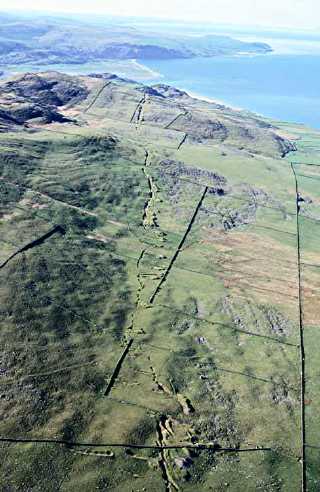 Photograph © Crown Copyright: RCAHMW |
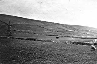
Aerial view of workings
The continuous line of workings of Egryn and (further from the camera) Hafotty seen looking south. The head end of the aerial ropeway is in the enclosure betwwen the two walls that meet at an accute angle near the bottom right of the picture. |
|
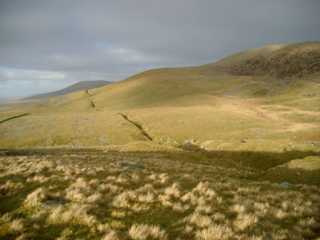 |
Workings
Some of the continuous line of workings of Egryn and (nearer to the camera) Hafotty seen looking north across Llwyn-du Parc from SH616186. The dark hill in the background aligned with the workings is Moelfre. Moelfre and Hendre mines are on the far side of it. The tips just visible in the foreground are those of the north end of Hafotty mine. |
|
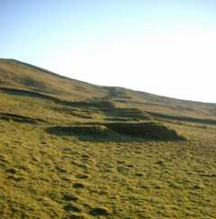 |
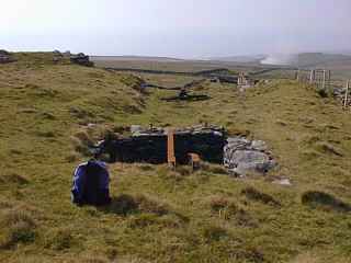
Tips
Looking south along the line of the workings from SH61841988. |
|
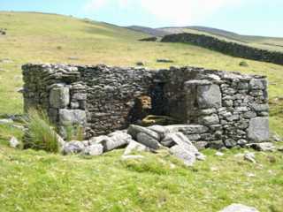 |
Smithy
The smithy at SH619203. A cutting which is possibly the remains of a collapsed adit entrance can just be seen on the right of the picture. |
|
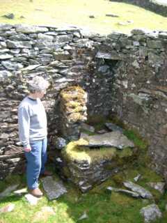 |
Smithy Hearth
The flue is behind the small lintel across the corner of the building. It is possible that there was a hood over the hearth supported by the stub wall on the left and the projecting stone on the right. |
|
The aerial ropeway system (Roe’s Patent) was brought into use in March 1917. It ran for 2.2km to SH595203 [OS 1918: 116] due east of Egryn Abbey iand is assumed to be gravity operated. From the lower terminus the ore was hauled a further 1.6km to the railway at Talybont Halt (SH585215), “by traction”. [GAS CAO: XD/35/424 p. 157]
An account of the ropeway [Edwards 1991] suggests that problems with it were not uncommon with loaded buckets falling to the ground on occasion. Edwards estimates that the loaded buckets weighed four to five hundreweight (200–250kg).
The head end terminal is described as being “almost complete” in the mid-1980s but destroyed by 1991 [Hawkins 2006].
In 2002 a geophysical survey for an archaeological excavation on Mynydd Egryn located lengths of the aerial ropeway rope which had been overgrown by turf [Roberts, J 2002].
 Photograph © John Ruston 2000 |
Tension weight pit
The pit in the foreground contains a substantial cast concrete weight in a steel frame and the sheave wheel over which the tensioning cable ran. The remains of the RSJs which carried the sheave wheel bearing pedestals are visible across the top of the pit. In 1980 substantial coils of rusting steel cable could still be seen on the grass. The loading point (described below) is beyond (and at a lower level to) the short cutting visible beyond the pit. |
|
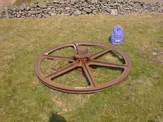 Photograph © John Ruston 2000 |
Main sheave wheel
Approximately 1.5 m diameter. It would have been carried in a sheave connected to the tension weight by a cable. |
|
 Photograph © John Ruston 2000 |
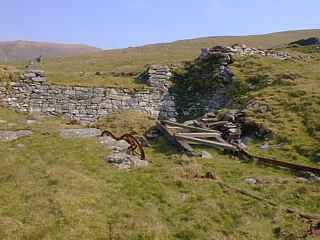
Loading point
The steel track visible on the grass in the foreground carried the transporter buckets (disconnected from the rope) whilst they were being filled. The timber framing which supported the track lies on the ground. Remains of cement rendering on the north wall of the loading area suggests that it may have been roofed in. The render has impressions of other components of the structure including a clear imprint of a door frame on the north wall which may have been an entrance door [Ruston 2000]. The embankment for the tramway from the workings can be seen upper right. |
|
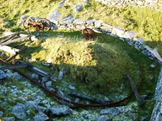 |
Loading point
Another view of the loop of steel track which carried the transporter buckets when they were disconnected from the rope whilst being loaded. Top left are a pair of support sheeves on a balance beam. |
|
 |
Loading point
The end-tipping dock at the end of the tramway from the workings can be seen upper centre. Edwards [1991] mentions horse haulage on the tramway to here with the ore being tipped onto the loading bank and shovelled into the ropeway buckets by hand. A waste tip is visible top right beyond the wall in the background. |
|
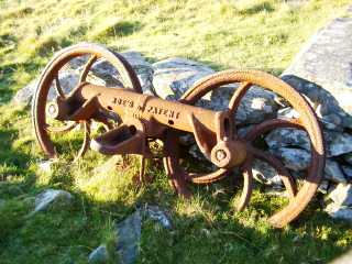 |
Balance beam and support sheaves
Detail of the balance beam and support sheaves which can be seen in the above pictures of the loading point. There are two such assemblies at this location. Roe’s Patent was for a single rope system (i.e. no separate suspension rope, the buckets being supported by the haul rope). At each standard the rope passed over two (as at Egryn) or four sheaves mounted on pivoted beams that aligned themselves to the rope and so equalised the load on each sheave. This allowed the standards to be spaced further apart, one example mentions a spacing of 250 yards on a 4000 yard long system. [Enc Brit 1911 v. 7 p. 64]. |
|
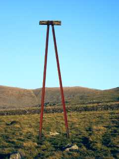 |
Ropeway support tower
This is the only remaining ropeway support tower near SH610204. It is constructed of bullhead rail. The other towers were wooden [Down 1980: 45]. It is possible that this tower was a replacement for an earlier wooden tower. There are two stones (foreground) with eye-bolts holes (one eye-bolt still in situ) in front of the tower and two more beyond the tower. Presumably they were anchors for wire stays to support the tower. Considering the distance of this tower from the ropeway head end and assuming a maximum interval of 200yd (183m) between towers there were probably at least 11 and possibly 12 towers on the ropeway. |
|
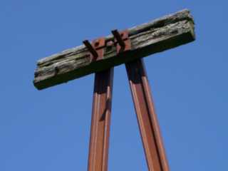 |
Top of tower
Detail showing steel rail uprights and wooden cross-piece. The pivoted beams carrying the sheeves (see above) would have been fixed to each end of the horizontal cross member. |
|
 Photograph © John Ruston 2000 |
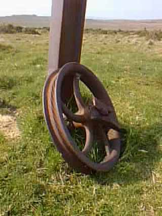
Carrying wheel at foot of tower
Note wear marks in wheel periphery caused by wire rope. The amount of wear visible on this and other wheels on the site suggests that the ropeway equipment might have been used elsewhere before being brought to Egryn. |
 |
Anchor stone and carrying wheel
One of the (presumed) stay anchors at the foot of the tower, a carrying wheel and a carrying wheel (or carrying wheel frame) mounting. |
 Photograph © John Ruston 2000 |
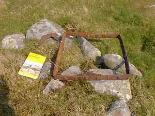
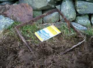
Riveted steel frames of buckets
The frame dimensions are aproximately .51 m x .53 m. The sides of the bucket slope in at about 20° to the vertical. The lower picuture is of another bucket frame at SH60052034 (December 2006). The upward-pointing tongue on the right-hand side of the frame would have been engaged by a catch on the carrying yoke – releasing the catch would allow the bucket to tip and empty its load. Some of the sheet iron material of the bucket is visible behind the frame. Both bucket frames appear to have been left on the route of the line. Local folk-lore has it that miners used to speed their journey to work by taking a (prohibited) ride up the mountain in the buckets. It must have been a tight squeeze considering the size of the frame. [Ruston 2000] There is also currently at least one surviving person who relates how he rode in a bucket as a child. [Jones, G 2002] |
|
 |
||
 Photograph © Executors of the late Moses Griffith |
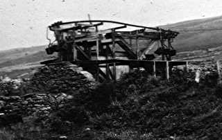
Ropeway tower and bucket
Wooden ropeway tower and one of the ropeway buckets near the lower terminus. The tower structure is a slender pyramid with cross and diagonal bracing. The balance arms for the carrying sheeves are mounted some way down from the top of the structure. This and the following two photographs were taken by Moses Griffith sometime between 1924 and 1941 when he was the tenant at Egryn. |
|
 Photograph © Executors of the late Moses Griffith |
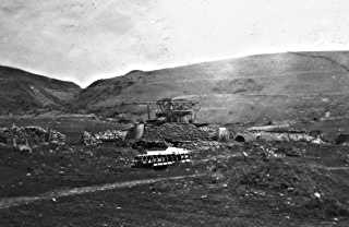
Ropeway terminus
General view of the lower ropeway terminus at SH59652031. The lack of visible cart or lorry tracks in the vicinity of the terminus suggests that the ropeway was no longer in use at the time of the photograph. To the left of the terminus there appears to be a hut with a cylindrical tank in front of it. There is another small hut (a privy?) to the right of the terminus. |
|
 Photograph © Executors of the late Moses Griffith |
Ropeway terminus
A number of buckets can be seen hanging from the carrying rail that runs around the structure, and there is one bucket lying on the decking below the carrying rail.
The construction is similar to the ropeway headend at the mine. There appears to be a discharge chute on top of the wall (centre left) above a built up loading platform, from which the ore would be shovelled into a lorry for transport to Talybont railway station. |